 Alignment Engineered Shafting Design
Many shaft, bearing, and coupling problems arise because little thought was given to alignment requirements during the design process.
For new or replacement shafting, Diehl Engineering Company will design the shafting arrangement so that it will not only perform its intended function, but also be flexible enough to optimize alignment sensitivity without incurring lateral vibration problems.
 Alignment Analysis
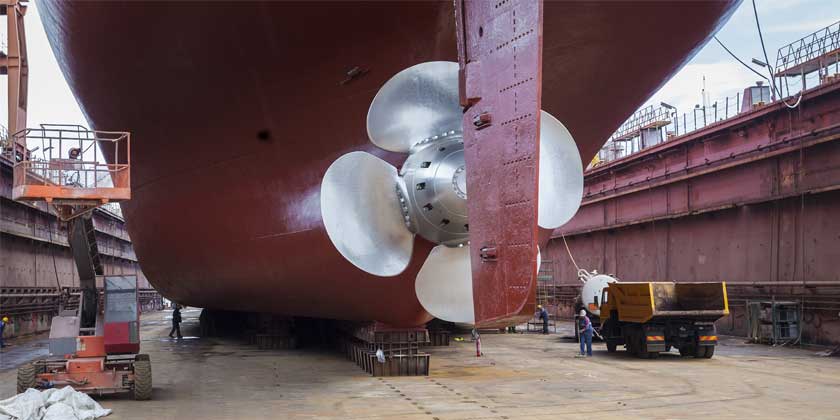
The first step in successful alignment of ship propulsion shafting is to determine what the alignment should be to satisfy all operating conditions over the stern bearing weardown range.
Diehl Engineering Company will perform an analysis of the shafting system to determine proper bearing offsets to achieve optimum bearing loading while minimizing shaft bending stresses. Our analysis utilizes our own proprietary computer modeling program, and considers such factors as bearing clearances, bearing weardown, thermal changes, reduction gear alignment to minimize gear skew, and whirling vibration.
DEC will integrate the results of alignment measurement via lasers, strain gages, and/or load cells, to determine existing alignment, provide recommendations for what to do to improve alignment, and measure the final results.
 Alignment Using Lasers
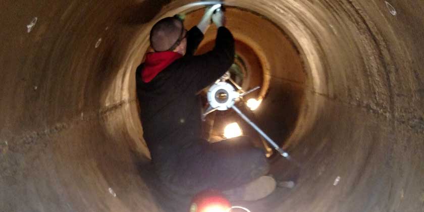
Diehl Engineering owns a full range of laser alignment tooling, including lasers, laser head holders, laser targets, and target holders, and will perform laser measurement of bearing offsets for a large variety of ships in drydock.
We will perform the required laser sightings using our own equipment, or provide oversight and technical assistance for the client’s laser sighting equipment. DEC will geometrically analyze the sighting results, provide charts showing vertical and athwartships bearing offsets versus distance along the shaft, provide instructions for re-boring stern and strut bearings, or re-positioning of lineshaft bearings.
 Alignment Using Strain Gauges
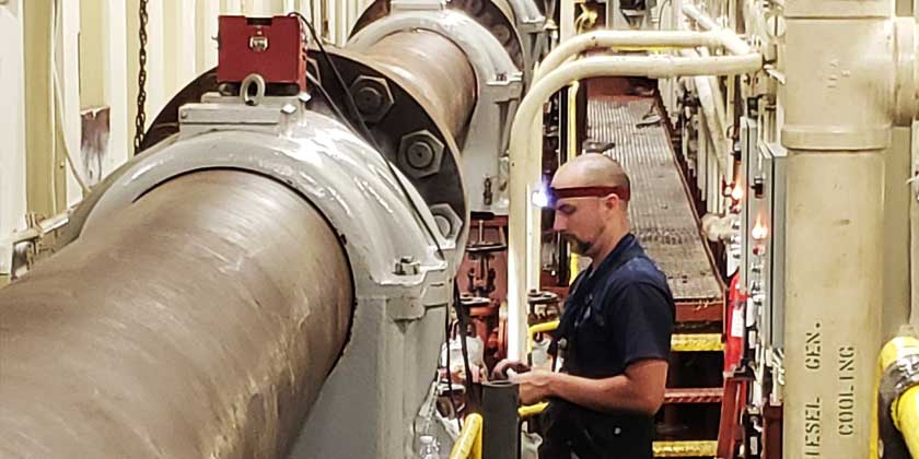
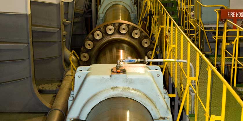
Shafting is properly aligned when desired vertical and horizontal bearing loads have been achieved within the range of acceptable shaft bending stress.
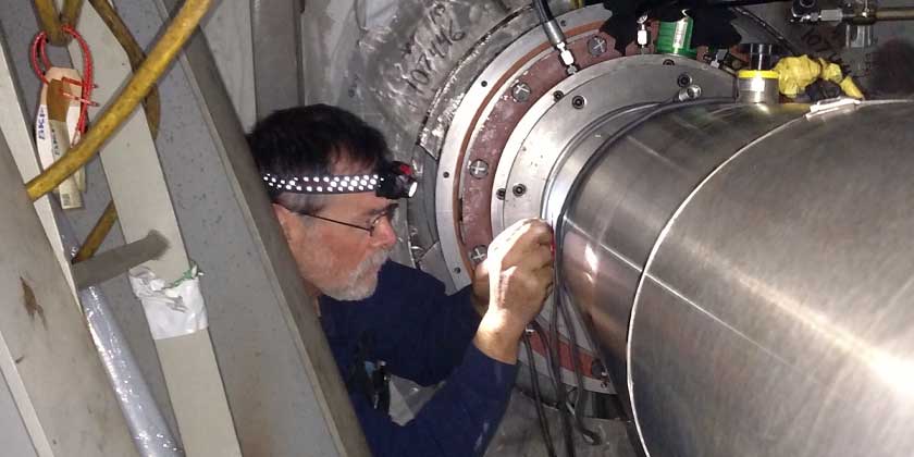
Diehl Engineering has a long record of successful alignment measurement using the strain gage method. We only use pre-wired, full bridge circuits containing weld-on gages and quality connectors. The number and location of the bridge circuits is chosen to optimize strain measurement accuracy within the constraints of each shaft arrangement. The resulting strains measured at each 90 degrees of shaft rotation, when entered into our proprietary program, yield the bearing loads that mathematically must exist to have produced the mix of measured strains.
We believe that we can reduce the time and expense spent on shaft alignment via the strain gage procedure, while achieving a superior alignment.
Diehl Engineering is certified in strain gauge alignment by the U.S. Naval Sea Systems Command (NAVSEA) to install and perform main propulsion shafting system alignment measurements on US Naval Ships using the strain gauge method. Click here to view our certification.
 Alignment Using the Jack and Load Cell Method
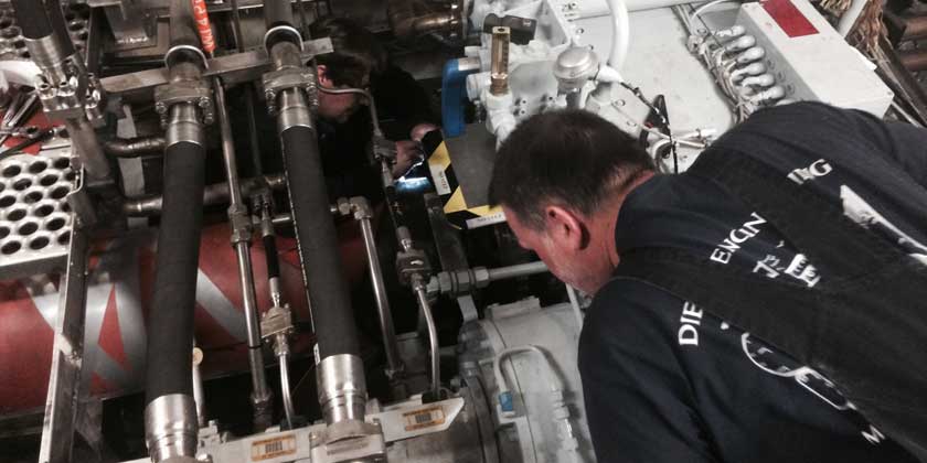
Diehl Engineering Company will measure bearing loads by the jack method as an alternative to the strain gage method, for those applications where this is either deemed more practical, or is preferred by the customer.
Using our load cells, we calculate jack location correction factors, and graphically plot the results to determine load and influence numbers for each bearing measured.
 Installation and Alignment Procedures
Diehl Engineering Company will provide clear, concise, detailed instructions for the installation and alignment of any shaft, engine, or mechanical power transmission system. We will also provide qualified and competent onsite supervision to ensure that a correct alignment is achieved.